Building Facts Brief
2751 E Oakland Park Blvd, Fort Lauderdale, FL 33306
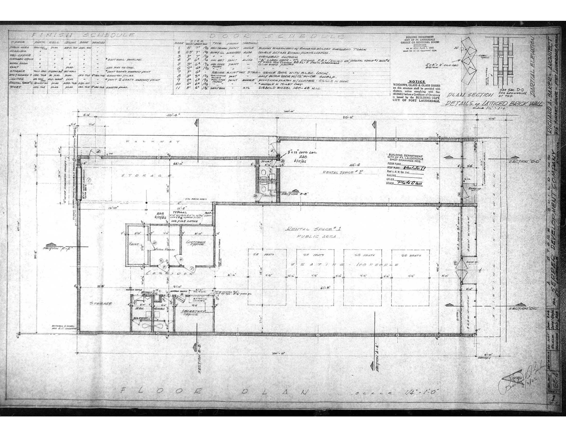
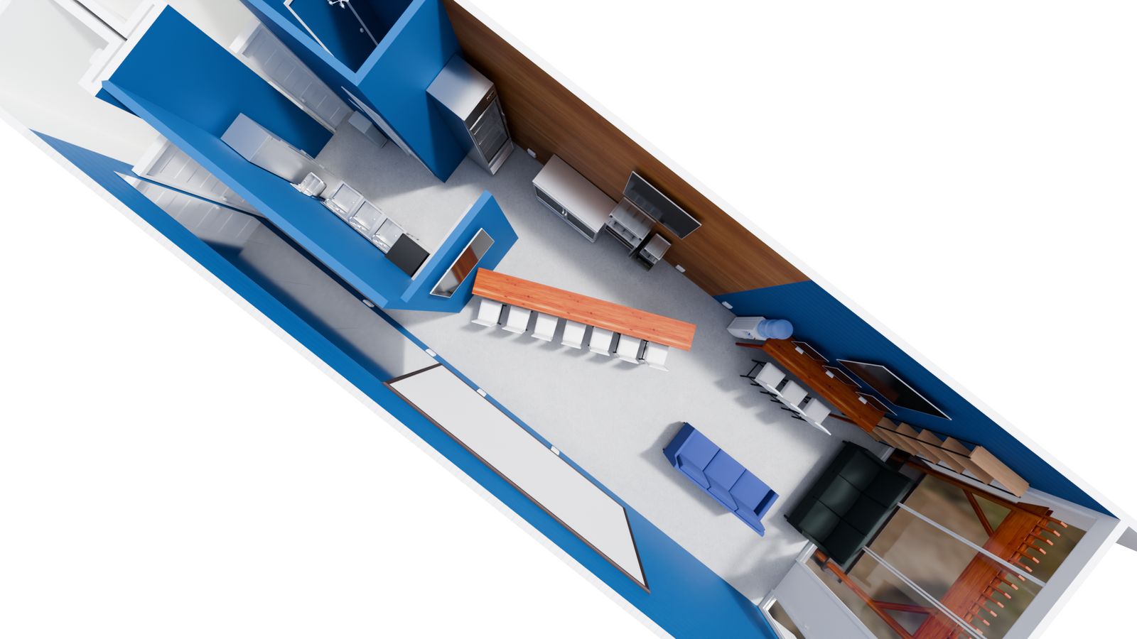
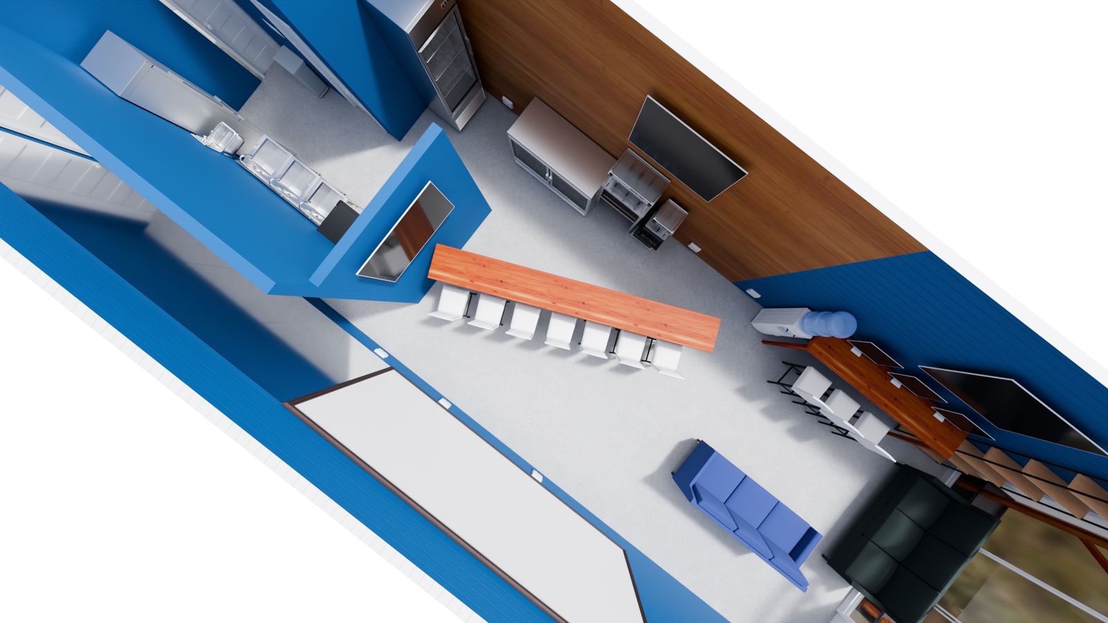
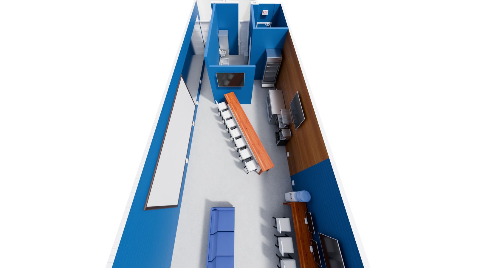
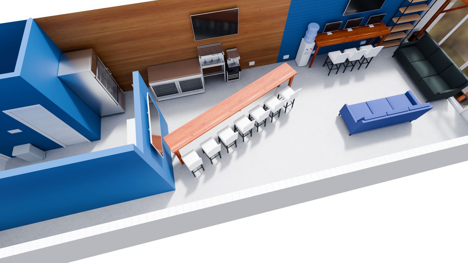
Proposed Floor Plan
The proposed layout as drafted. Shows the restrooms, owner’s office, kitchen with the new L-shaped wall, the 14-ft caster bar (movable equipment, N.I.C.), seating arrangement, and pergola lounge. Open the PDF for full vector resolution.
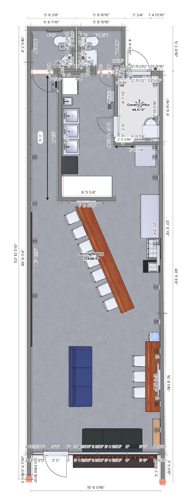
Download Proposed Floor Plan (PDF)
A. Building — Confirmed
| Address / Folio | 2751 E Oakland Park Blvd, Fort Lauderdale, FL 33306 · Folio 4942-24-03-0050. The building was originally filed in 1965 under 2749 E Oak Pk Blvd; the bay was renumbered to 2751 later. |
|---|---|
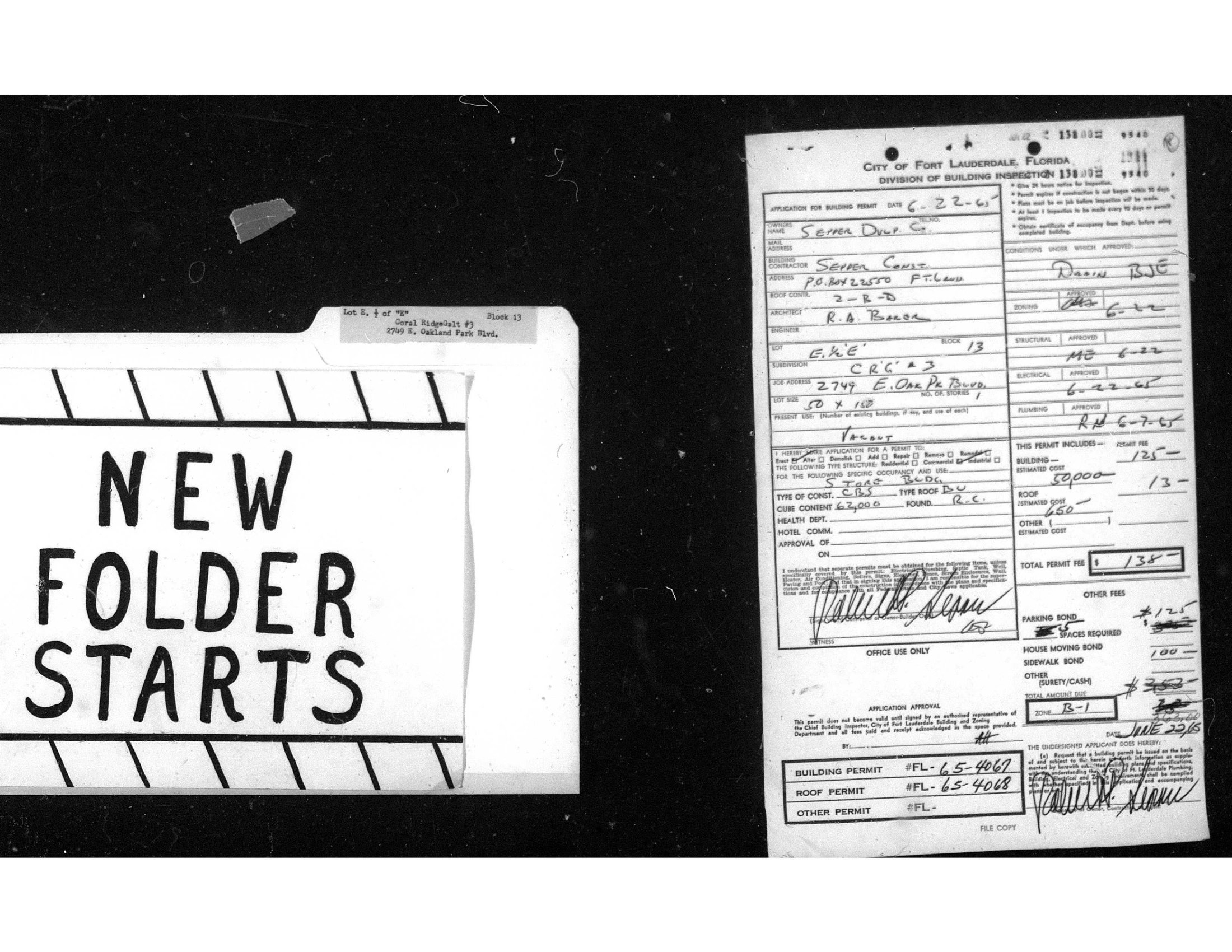
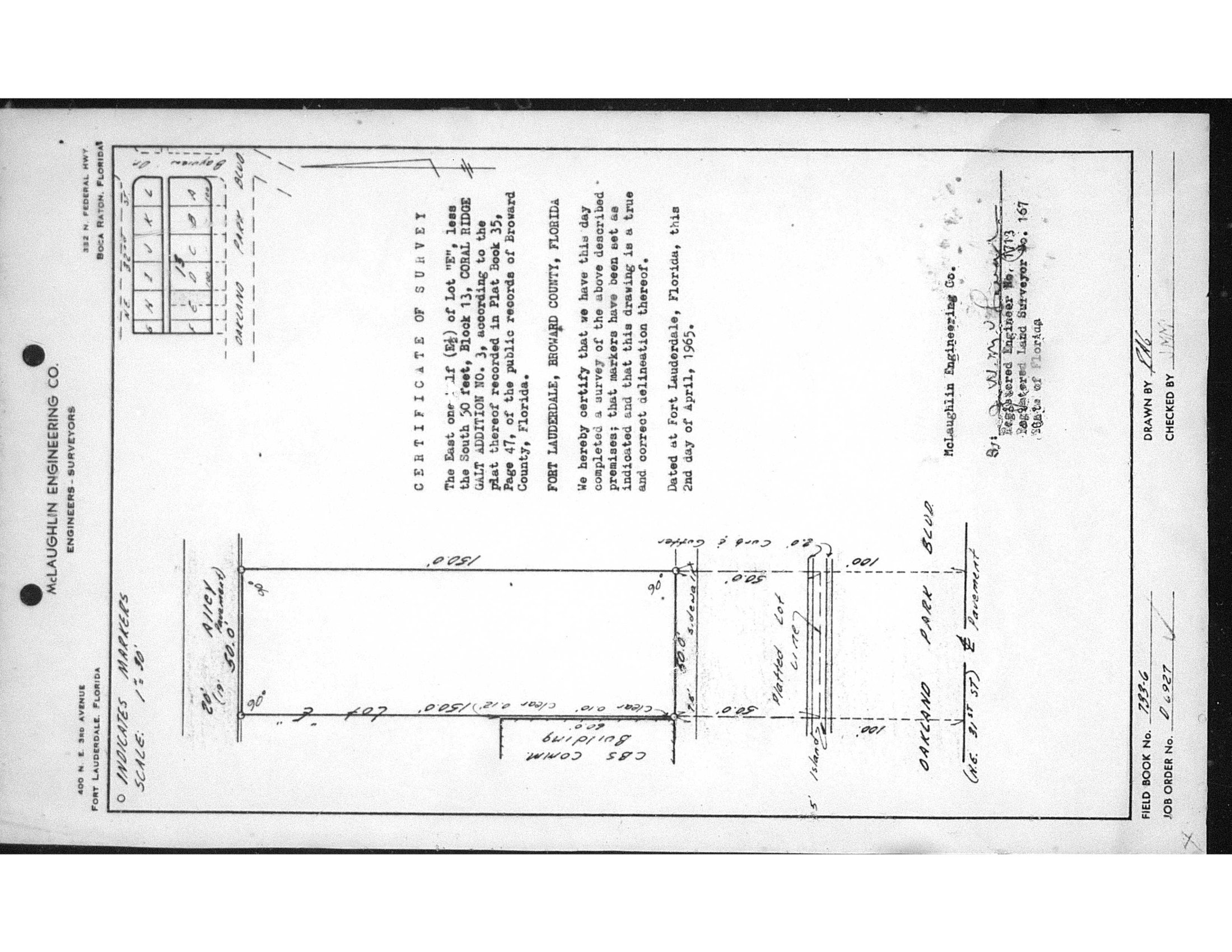
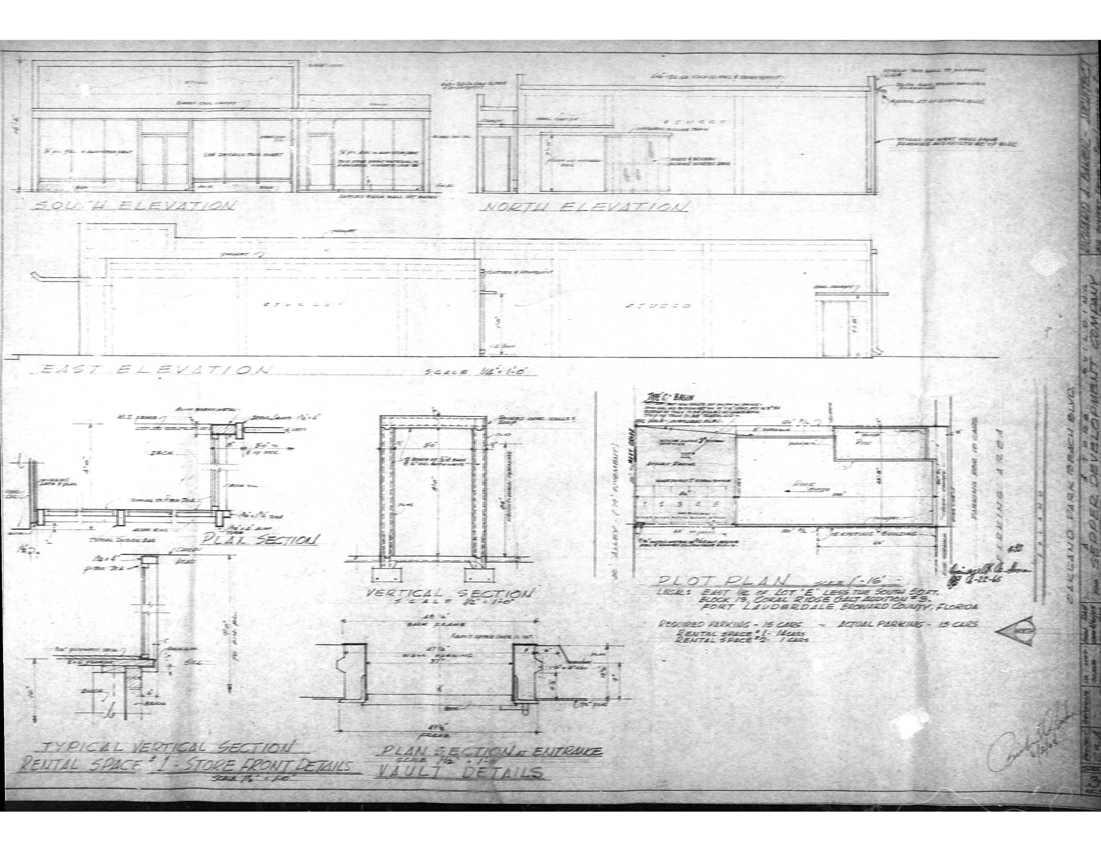
| Legal description | East ½ of Lot E, less the South 50 ft, Block 13, Coral Ridge Galt Addition No. 3 (PB 35, Pg 47, Broward County). Lot dimensions of record: 50 × 150 ft (per master permit p0022 + McLaughlin survey 4/2/1965, p0023). |
| Year built | 1965. Certificate of Occupancy #5388 issued October 19, 1965. |
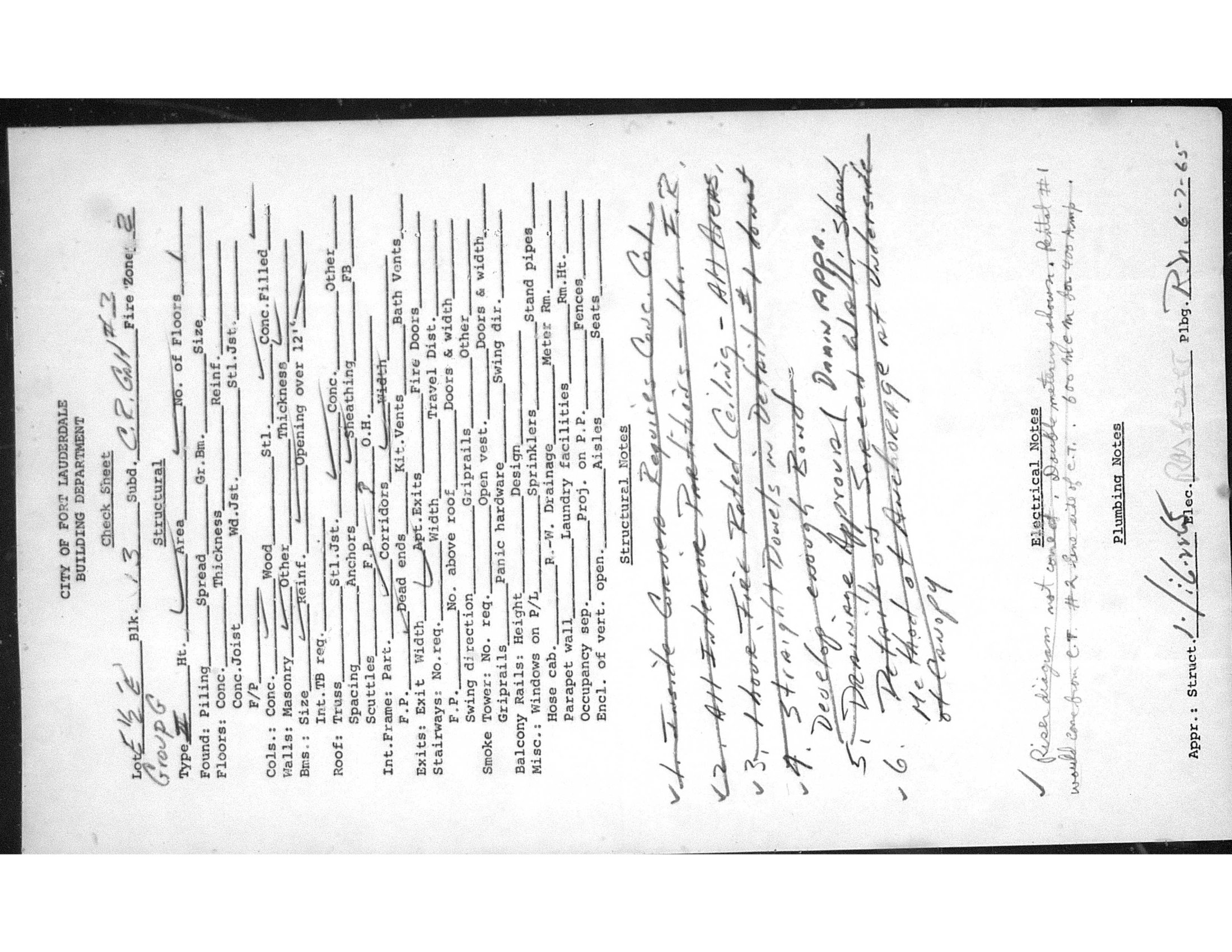
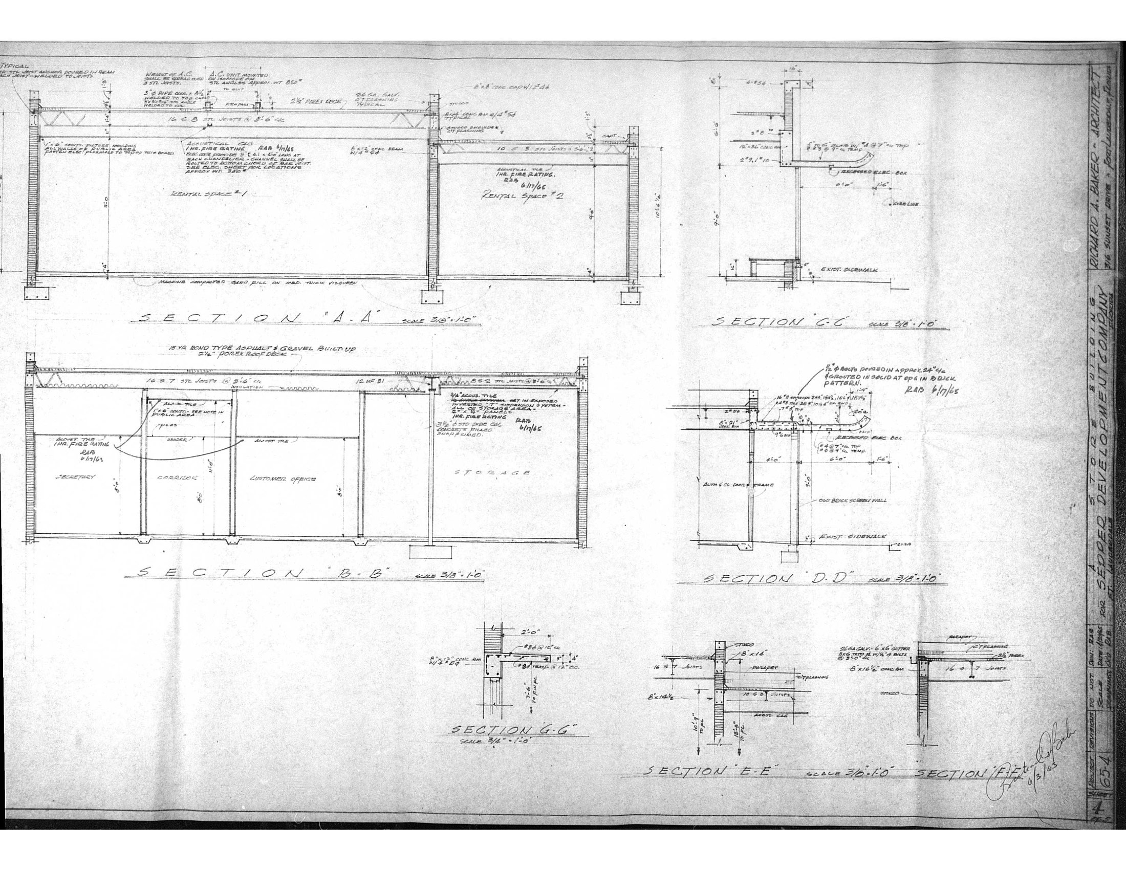
| Construction type / classification | CBS — concrete block, stucco exterior. Reinforced-concrete foundation. Classified Type II construction, Group G, Fire Zone 2 per 1965 South Florida Building Code (City plan check, p0024). |
| Structure / age uniformity | 2751 and the adjoining 2747 bay were built as one structure in a single 1965 construction event. Demising wall is 8-inch CMU. Structural system and age uniform across the suite. |
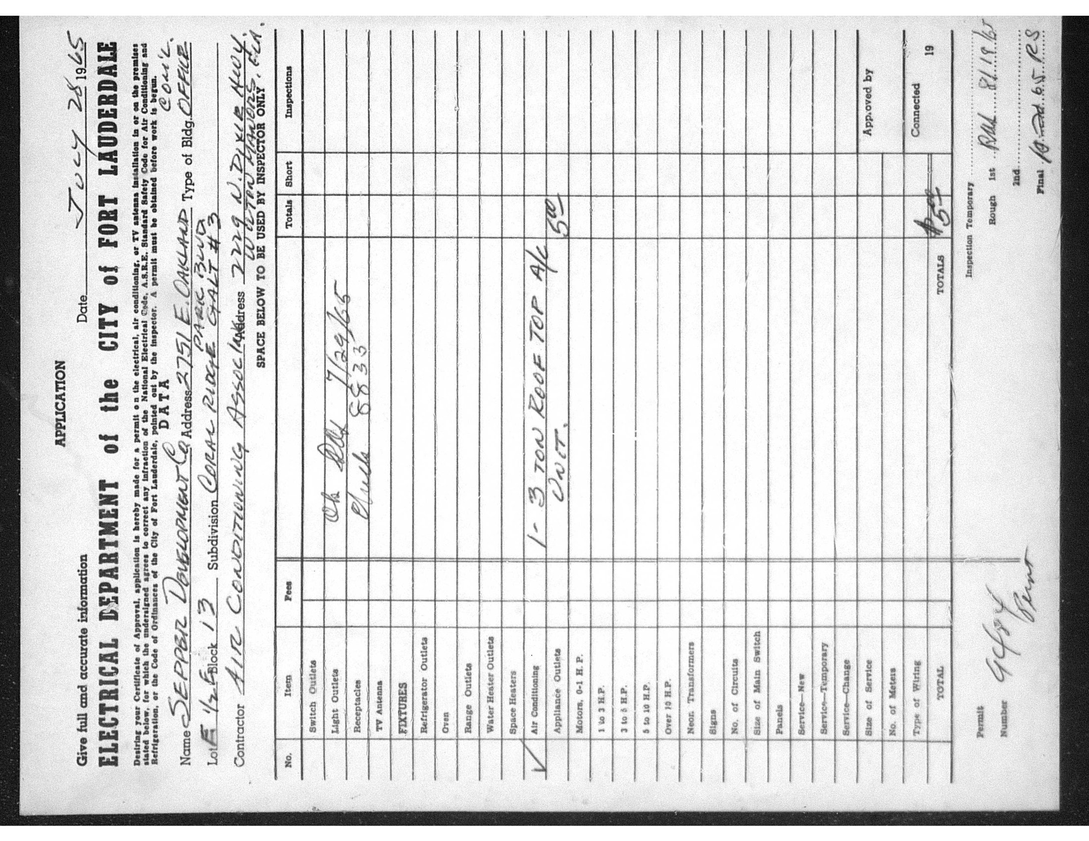
| Original permits (1965) | Building FL-65-4067 · Roof FL-65-4068 · Original A/C permit #9484 (3-ton electric rooftop, Air Conditioning Associates, 7/28/1965). Architect: Richard A. Baker. Owner: Sepper Development Co.; Original GC: Sepper Construction. |
B. Interior & Systems — Confirmed (Existing Conditions)
| Existing interior layout | Current interior partition layout is a 1982 tenant build-out (Chisholm Realty, permit #82-7116, Robert Brewster Construction). It is not original 1965 fabric — existing non-structural partitions are 1982-era. |
|---|---|
| Original fire-rating regime (1965) | 1965 plan check (p0024) required 1-hour fire-rated interior partitions and 1-hour fire-rated ceiling throughout. |
| Drainage | 4″ cast-iron soil stack present; visually confirmed at three points. |
| Customer restroom and employee restroom | Both rooms are retained as-is. Existing fixtures — toilets, sinks, exhaust fans, light fixtures, switches, and outlets — all remain. Scope is limited to: (a) adding two ADA grab bars in the customer restroom; (b) lining walls and ceilings with FRP in both restrooms; (c) the sink swaps below. No fixture relocation, no new plumbing rough-in, no door changes. |
| Sink swaps | (1) The existing employee restroom sink was previously swapped for a utility / mop sink. (2) The customer restroom vanity was previously swapped for a wall-mounted corner sink to maximize interior floor space for ADA access. Both swaps used the existing supply and drain points and are in place today — shown on drawings as existing. |
| Bathroom entry door | Existing 32″-wide louvered door (32″ slab / 32″ clear), outswing with door closer. Existing condition; no change. |
| Water heater | Existing original water heater located in the attic space directly above the bathrooms. Existing condition retained. (Unit model number available on request.) |
| Electrical — original 1965 service | 400 Amp main, dual metering, EMT wiring (per p0024). Service has since been downsized. |
| Electrical — current main panel | Frank Adam, 125A, 20 slots. Installed 2008 (Albert Siefert, EC0002423, permit PM-08120788). |
C. Permitted Scope of Work
C.1 Scope Summary
This permit’s scope, in priority order:
- The headline new construction: the L-shaped kitchen wall and the plumbing and electrical feeding into that wall (see C.2).
- Restroom modifications — minimal: two ADA grab bars in the customer restroom; FRP wall/ceiling lining in both restrooms; sink swaps already completed in both (employee → mop sink; customer vanity → wall-mount corner sink) — shown as existing. Existing toilets, exhaust fans, lighting, switches, and outlets remain in place. (See C.3.)
- Mop / service sink — FDACS compliance, shown at the existing employee restroom fixture location (see C.4).
- 14-ft caster bar — planned as movable equipment, N.I.C. (open engineering inquiry — see C.5).
- Anything else the engineer or building official flags as required to permit and install the above. The goal is permit issuance, build, CO, and FDACS clearance on the shortest defensible path so the business can open and stop carrying rent at two locations.
C.2 Kitchen — New L-Shaped Wall + Feeds
The major new construction. New L-shaped kitchen wall with the plumbing and electrical feeding into that wall. See Section G (Proposed Designs — Kitchen) for layout intent.
C.3 Customer Restroom — Maximum Extent Feasible
Existing CMU-bound room (~52.75″ × 59.5″) cannot meet full 60″ ADA clearance / turning space; CMU walls are a hard structural constraint. The restroom proceeds as maximum extent feasible per ADA §202.3 / FBC-EB §306.6. Sealed technical-infeasibility memo accompanies the set, citing Access Board Guide to ADA Standards Ch. 2 (Feb. 2014) and DOJ Title II preamble on plumbing-wall infeasibility.
Governing codes: 2010 ADA Standards · FBC-Accessibility 2023 · FBC-Building 2023 · FBC-Plumbing 2023 · FBC-Existing Building 2023 (8th ed.) · ICC A117.1-2017.
Scope is limited to the items below. The existing water closet, exhaust fan, lighting, switch, and outlet are retained — no fixture relocation.
| ADA grab bars | Two grab bars added: side grab bar 42″ min (33–36″ AFF, 12″ max from rear wall, §604.5.1) and rear grab bar 36″ min (§604.5.2). Anchored directly into the CMU walls with appropriate masonry anchors. |
|---|---|
| Wall-mount corner sink (existing — vanity previously swapped) | The vanity was previously removed and replaced with a wall-mount corner sink with minimal footprint, tucked into the corner to maximize floor space and ADA approach — shown as existing. Rim ≤ 34″ AFF (§606.3); knee 27″ h × 8″ deep (§306.3); toe 9″ h (§306.2); lever or touchless faucet (§309.4); §606.5 pipe protection on supply, drain, and P-trap (foam wraps, Truebro/Lav-Guard or equivalent). Connected to the existing supply and drain points at the wall. |
| FRP wall & ceiling lining | Walls and ceiling lined with FRP (fiberglass-reinforced plastic) panels. Smooth, nonabsorbent, cleanable surface; aligns with FDACS sanitation expectations. |
| Door (existing — no change) | Existing 32″ louvered slab door, outswing, with door closer. Already meets the accessibility criteria for an existing-building restroom door. No widening, no swing change. |
C.4 Mop / Service Sink — Employee Restroom
Required — FBC-Plumbing Table 403.1 (Note h) waives the service sink only for Business/Mercantile occupancies with an occupant load of 15 or fewer — at ~38 occupants this space exceeds that ceiling, so the service sink is required. Shown on drawings at the existing employee-restroom fixture location: the existing employee sink was previously swapped for a utility / mop sink at the same plumbing connection, and the mop sink is in place today. For the city plan-review track this is straightforward — shown as a pre-existing fixture, no new rough-in.
C.5 Caster Bar — Engineering Inquiry (Movable Equipment, N.I.C.)
Concept: a 14-ft single solid top on lockable rolling casters. Countertop is custom-built and -shaped wood-plywood construction, finished with food-grade clear coat and flexible plastic edge banding. The plan is to show the bar on drawings as movable equipment / N.I.C., not as fixed construction, so that no structural or electrical inspection is triggered. To hold that classification it would: not be anchored to floor or walls; carry no plumbing and no hardwired electrical (cord-and-plug only); and be positioned so it does not block required egress or the accessible route. Strings that still apply regardless of “movable” status:
- ADA §904.4 accessible service-counter segment wherever customers pay: ≥ 36″ long at ≤ 36″ high (parallel approach; 30″ × 48″ clear floor space) or ≥ 30″ long with knee clearance (forward approach). Build into one bar module.
- FDACS: food/drink contact surfaces smooth, nonabsorbent, cleanable (NSF-style). Sealed top, no raw-wood contact surface. The proposed wood-plywood + food-grade clear coat + plastic edge banding is intended to satisfy this.
- Movable-equipment classification: is the bar — as described — acceptable to show on drawings as movable equipment / N.I.C., with no structural or electrical inspection? If yes, what construction parameters do we have to hold to so it stays in that classification? Specifically: does the bar need a structural wall or cabinet base of certain height/depth, or is a structurally stable solid top on locking caster legs (effectively a rolling table) sufficient, provided it meets the ADA height/depth/clearance requirements and is stable under expected loads?
- Pass-through and barrier requirement at the end of the bar: we want a free-flowing, non-restricted open walkway from behind the kitchen, through the area behind the bar, and out to the customer seating area — so a single bartender can step out to provide floor service. Is that acceptable, or is a barrier / wall / doorway required between the customer area and the employee-side area at the end of the bar? If a barrier is required, what is the minimum acceptable construction?
- ADA §904.4 lower-section placement: can the §904.4 accessible service-counter segment be located near the pass-through area at the end of the bar — the same area the bartender walks through to provide floor service? Or does it need to be located elsewhere along the bar?
- Minimum viable opening configuration: if option 1 above is acceptable, our plan is to open with a rolling table form-factor (solid top on locking caster legs, no solid pass-through barrier beneath, structurally stable under load). Confirm acceptable, or specify what minimum upgrade is required to be code-defensible for opening day.
C.6 Engineering Notes to Carry on the Drawings
Synthesis of the items that should appear on the stamped set, plus the expected stamped-set components in one place:
To show on the drawings:
- Kitchen L-shaped wall + plumbing and electrical feeds into that wall (the headline new construction)
- Customer restroom: two ADA grab bars (anchored into CMU), FRP wall/ceiling lining, existing wall-mount corner sink (vanity previously swapped) with §606.5 pipe protection; existing WC, exhaust fan, lighting, switch, outlet retained
- Employee restroom: existing utility/mop sink (previously swapped at the same plumbing point), shown as pre-existing; FRP wall/ceiling lining; existing toilet and other fixtures retained pending FDACS posture (see C.4 inquiry)
- Existing 32″ outward-swing louvered restroom door with closer (no change)
- Existing original water heater in attic above bathrooms (no change)
- Frank Adam 125A main panel (existing, location annotated)
- 14-ft caster bar shown as movable equipment / N.I.C. with the ADA §904.4 service-counter segment called out (subject to confirmation per C.5)
- Restroom documented as maximum extent feasible per ADA §202.3 / FBC-EB §306.6 with the sealed technical-infeasibility memo accompanying the set
Expected stamped-set components:
- Cover / code-summary sheet — occupancy class (target Group B, <50 occ), occupant load, code editions
- Life-safety / egress plan
- Architectural floor plan — partition layout, finishes
- ADA / accessibility plan + details — grab bar locations, wall-mount corner lavatory, §904.4 service counter, accessible route
- Plumbing plan — kitchen feeds; existing mop sink and corner sink shown as pre-existing
- Electrical plan — kitchen feeds, panel/circuits (incorporating Freddie’s sketch), lighting, new loads
- Mechanical — AC (pending nameplate confirmation) + ventilation
- Engineer’s calcs — Florida Energy Code forms (change of occupancy), occupant-load calc, sealed technical-infeasibility memo (restroom MEF)
- Caster bar shown as movable equipment / N.I.C.
D. Pergola Lounge — Future-Phase Engineering Inquiry
Not in current permit scope. Future-phase consideration; expense deferred. We want your engineering opinion now so we can plan and budget for it correctly when the time comes. The concept is an outdoor bench / lounge seating area in the rear yard (see Proposed Floor Plan for intended location).
The core question: must a pergola lounge of this kind be a fixed, permitted, anchored structure, or is there a viable path to build it as freestanding movable equipment — analogous to the caster-bar approach — without triggering a building-permit cycle?
We did the initial research so you have the regulatory landscape at a glance:
- Fort Lauderdale ULDC §47-19.2 (freestanding shade structures — pergolas, gazebos, tiki huts, trellises): maximum height 12 ft, maximum size 200 gross sf, must be open on all sides; minimum 5 ft from rear property line (10 ft if abutting a waterway). The ULDC language is residential-context-heavy; commercial application would be confirmed with FTL Zoning.
- Broward County HVHZ (entire county): 170 mph design wind speed per FBC 8th edition (2023) referencing ASCE 7-22. Any permitted detached outdoor structure must be engineered to HVHZ; Broward County Code Division requires signed and sealed engineering drawings from a Florida-licensed PE for a detached pergola.
- FBC §105.2 — Work exempt from permit (potentially in play):
- One-story detached accessory structures used as tool/storage sheds, playhouses, and similar uses, where floor area ≤ 120 sf.
- Nonfixed and movable fixtures, cases, racks, counters, and partitions not over 5 ft 9 in (1,753 mm) in height.
- Note: a permit exemption does not waive other FBC requirements (wind load, zoning, setbacks) and does not authorize work that violates the code.
- Miami-Dade (similar HVHZ jurisdiction) precedent: “Pergola and trellis (lattice work) that are non-roofed / non-wind-resistant structures” are exempt from a building permit but still require a Zoning Improvement Permit. Suggests that a fully open, non-roofed lattice / trellis may have a lighter permit path than a roofed pergola, but this would need to be confirmed locally for Fort Lauderdale.
- For this commercial property in Broward HVHZ, is there a viable code path to build a freestanding outdoor bench / seating area as movable equipment (under 5′9″ height, no anchoring, no roof, no wind-resistant elements, ≤ 120 sf footprint, open on all sides) without triggering a building permit?
- If shade is desired, can the shade element be cloth (umbrellas / fabric awnings) on movable frames rather than a built pergola roof, in order to keep the assembly in the “non-wind-resistant” classification?
- What specific construction parameters — height, footprint, materials, anchoring restrictions — keep the assembly in a permit-exempt / movable-equipment classification under HVHZ rules?
- If a permitted approach is the only realistic route in Broward HVHZ, what is the order-of-magnitude complexity (engineering scope, wind-load calc, sealed drawings, NOA / product approvals) for a small (< 200 sf, < 12 ft high, open-sided) commercial pergola?
- Setback and zoning observations for this site (50 × 150 ft lot, rear-yard area) — anything you would flag now so we can plan around it?
- If we proceed with a built / permitted pergola later, the work would be its own permit cycle and would not be included in the current change-of-occupancy permit submittal. Confirm that’s the right sequencing.
E. Change-of-Occupancy Design Items (General)
Proposed use: botanical / kava beverage lounge. No alcohol. No commercial cooking — plug-in appliances only. The following govern:
- Occupant load & group: calculated ~38 at 15 SF/person — Group B, <50 threshold (IBC §303.1.1). Holding under 50 keeps fixture ratios in the gentler Group B lane and supports the single-restroom count. Crossing to 50+ flips occupancy to Group A-2 (assembly): heavier fixture ratios, and public restrooms must satisfy the 3:2 women’s water-closet requirement. Tune seating to maintain.
- Life safety: at this load/occupancy, assessed as not requiring sprinklers or a fire-alarm system, single exit acceptable (FBC 2023 + NFPA 101). For your confirmation.
- FDACS sinks — three required: dedicated handwash, 3-compartment, mop/utility (C.4).
- Energy calculations: required for the change of occupancy (FBC Energy Code, C503).
- ADA & accessibility: inspection is separate from final — accessibility designed in from the start. Restroom carries a sealed technical-infeasibility memo (see source note).
- DBPR — not triggered for this scope. Phase 1 beverage / prepackaged is statutorily excluded under Fla. Stat. §509.013(5)(b)7.. (Air fryer is a later-phase concern, deferred.)
Download this brief (Word .docx)
F. Primary-Source References (1965 Microfilm)
Seven original 1965 microfilm pages from the City of Fort Lauderdale records — the source of record for Sections A and B. Click any image for full resolution.
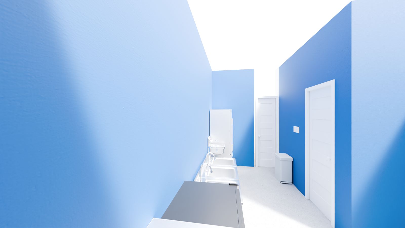
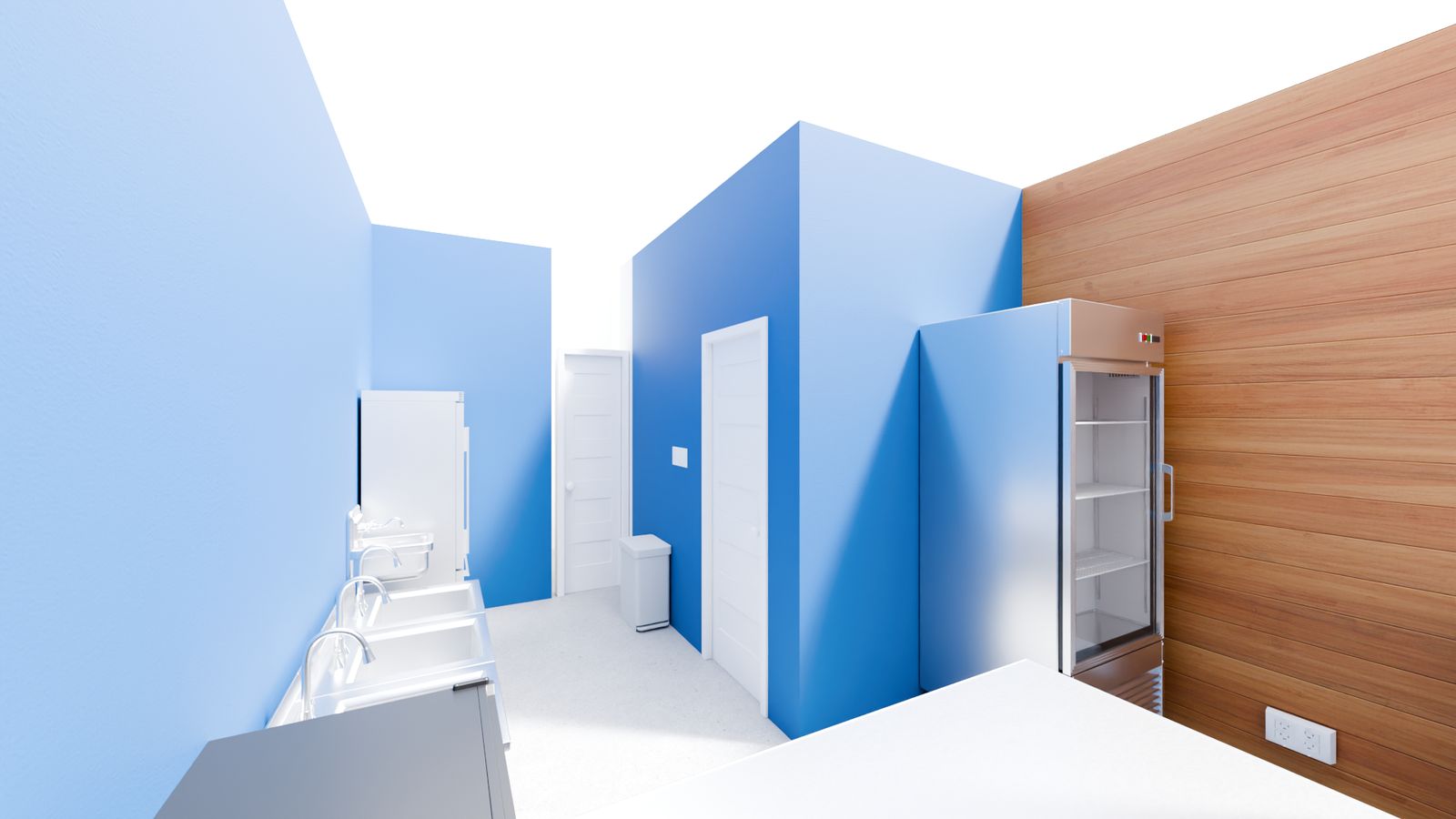
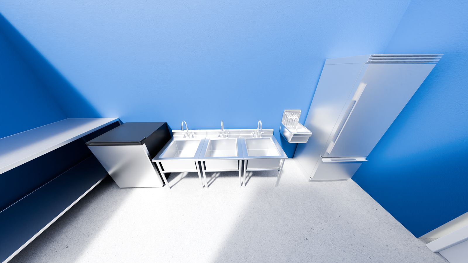
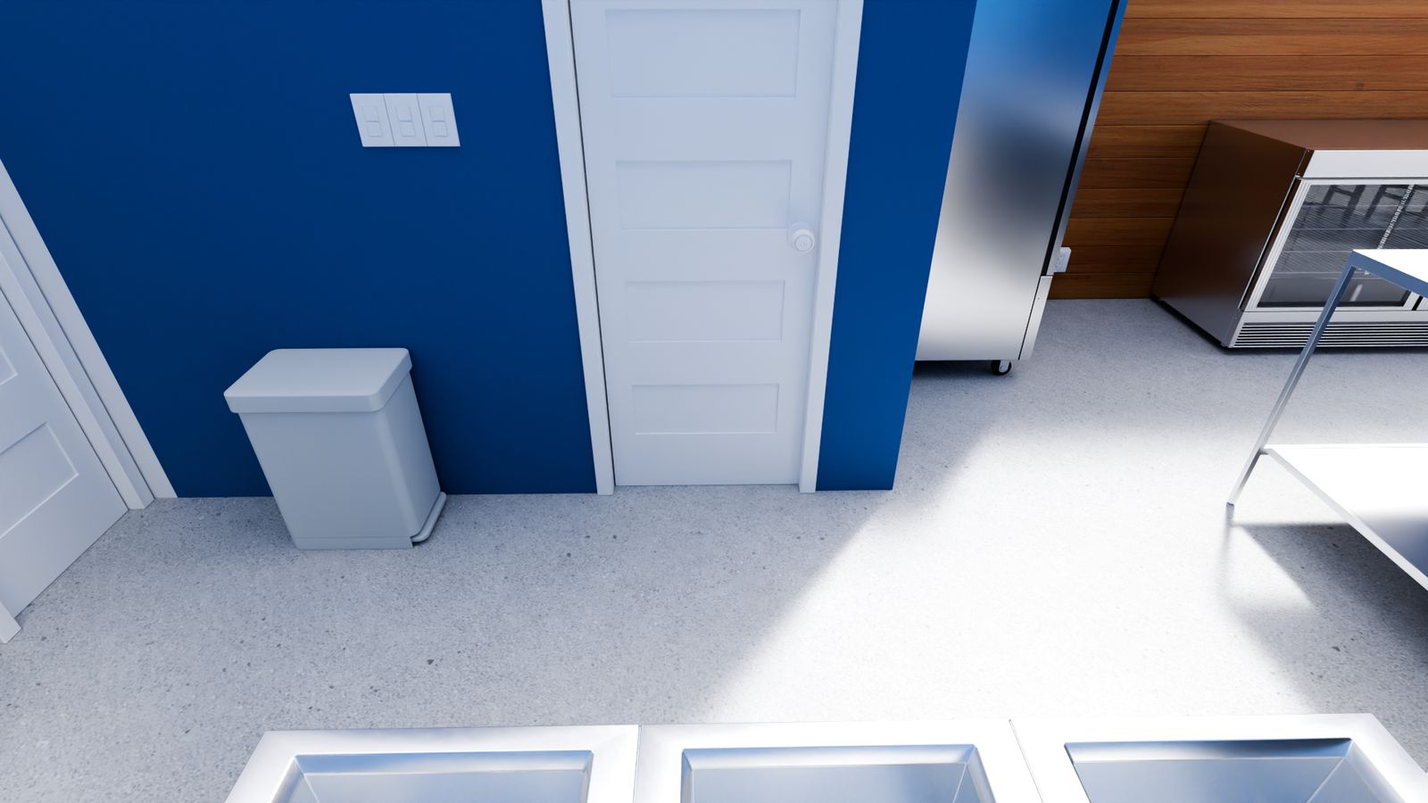
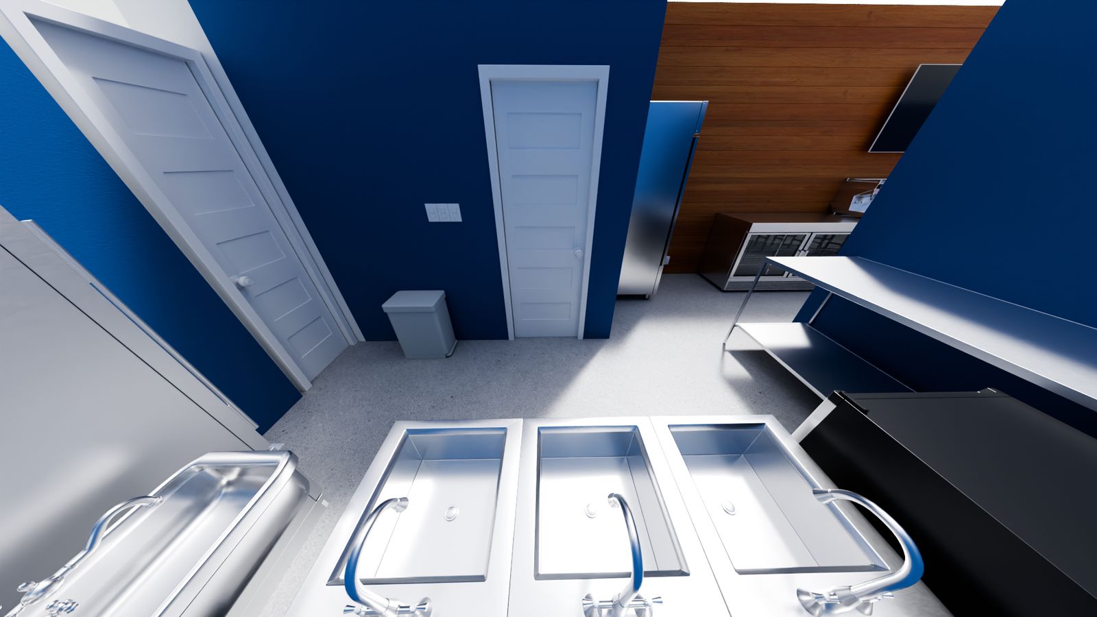
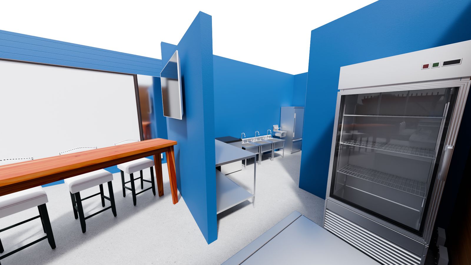
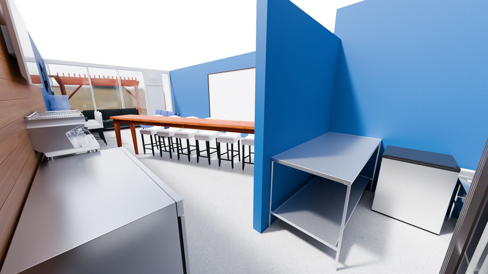
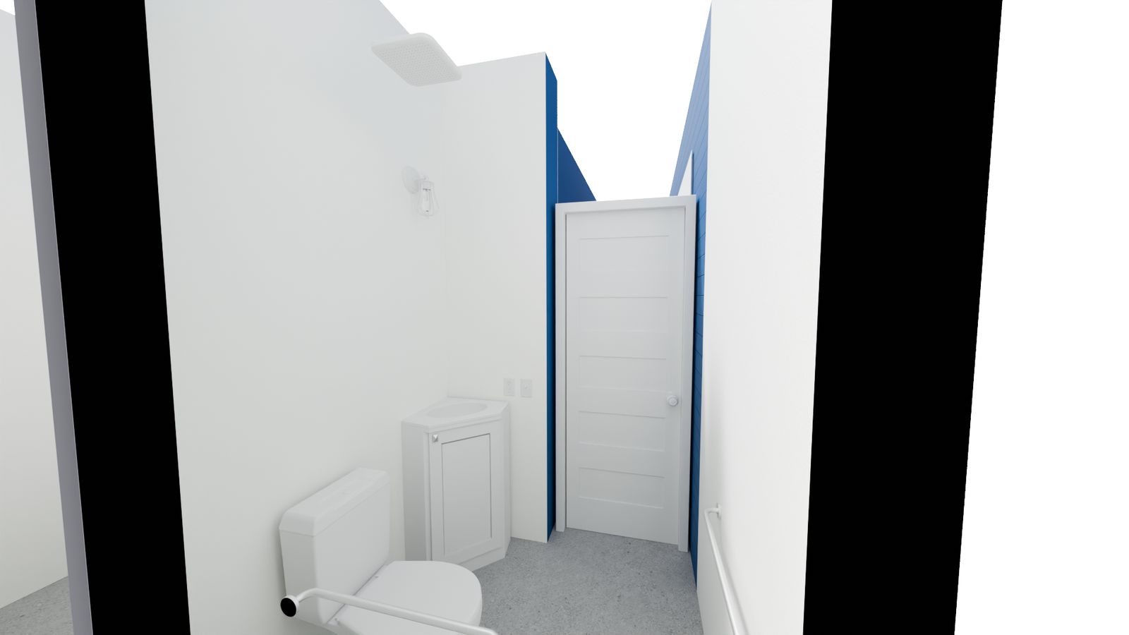
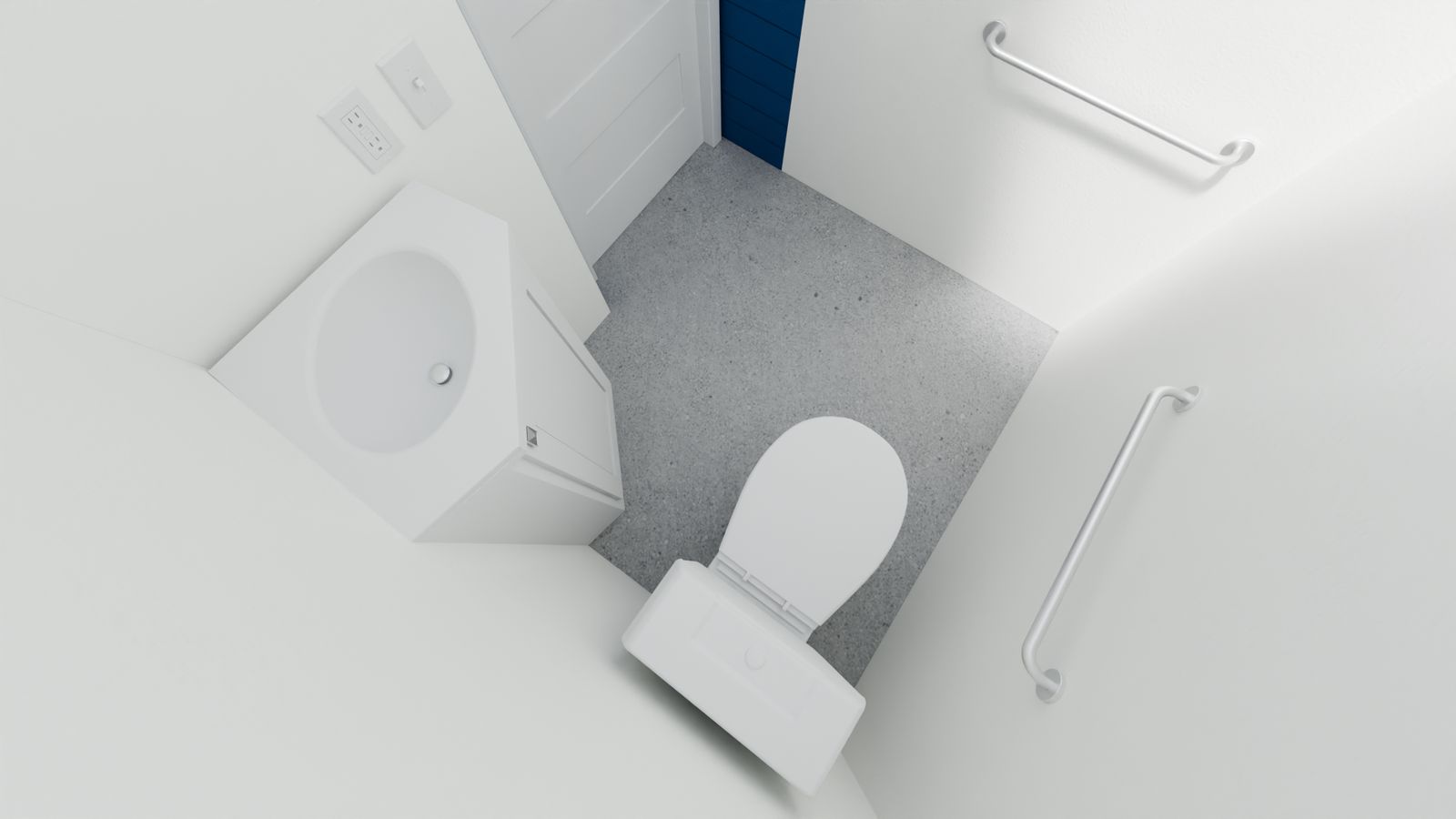
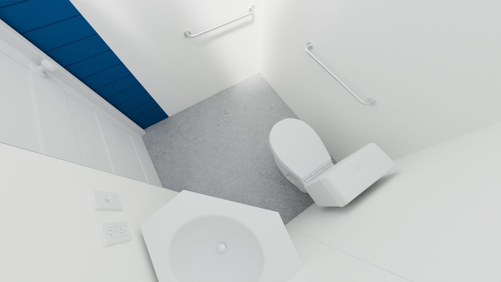
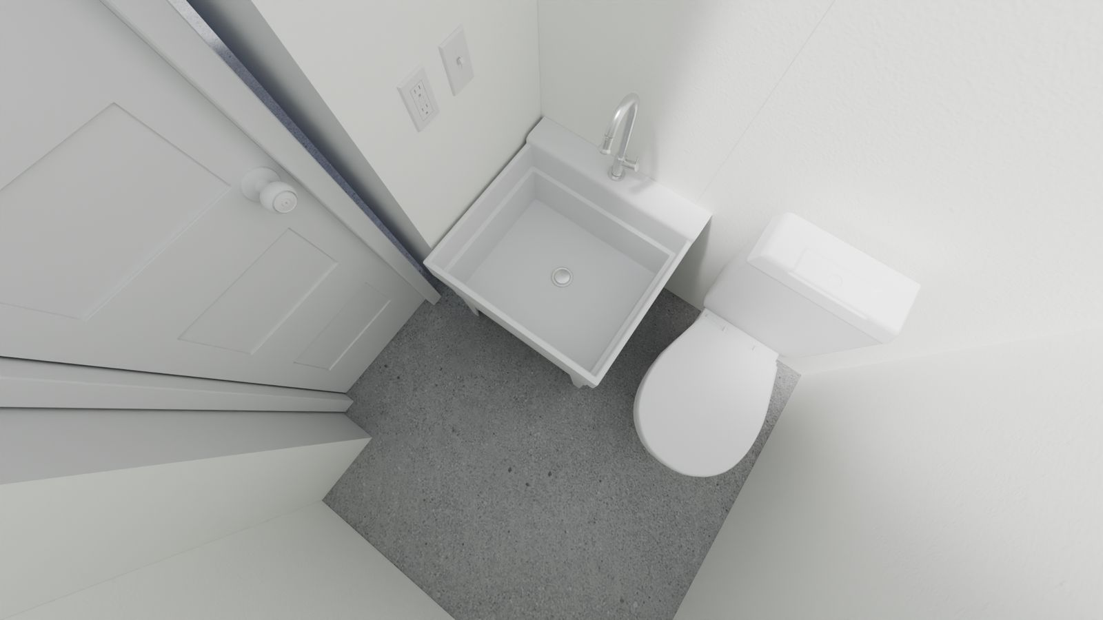
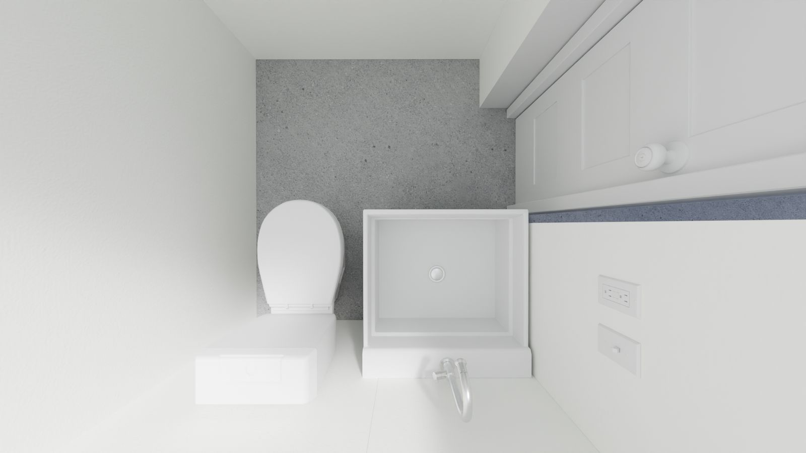
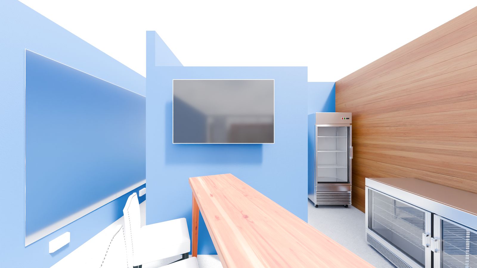
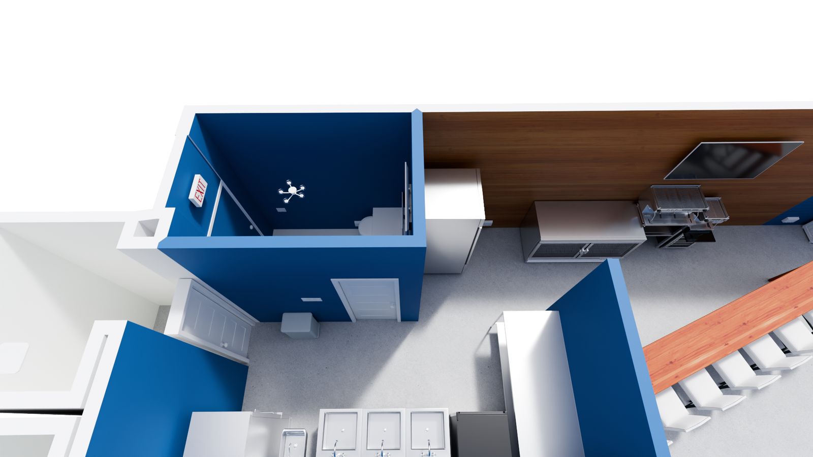
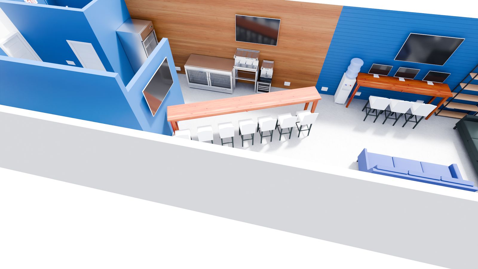
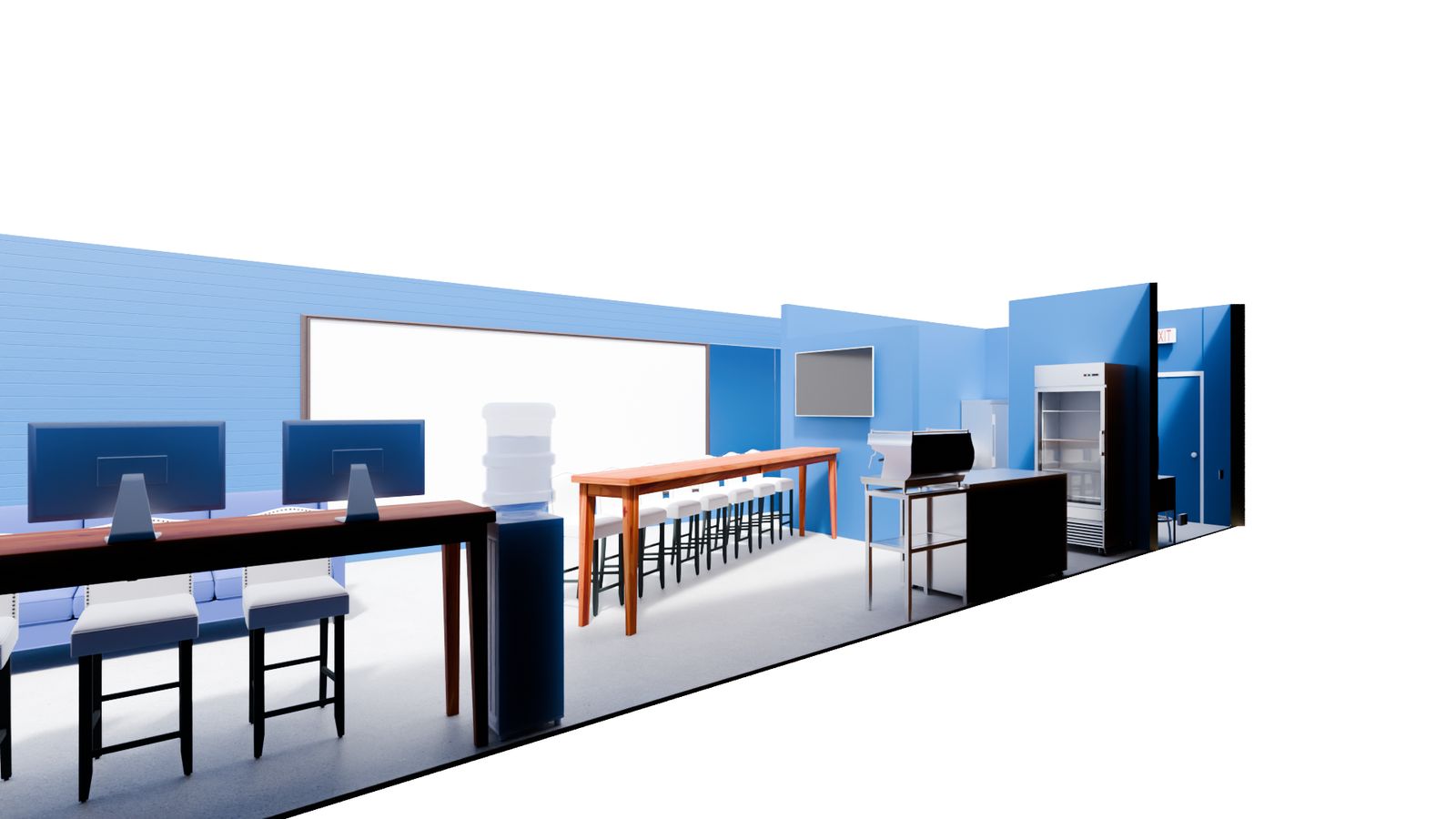
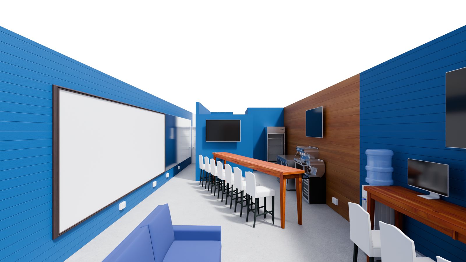
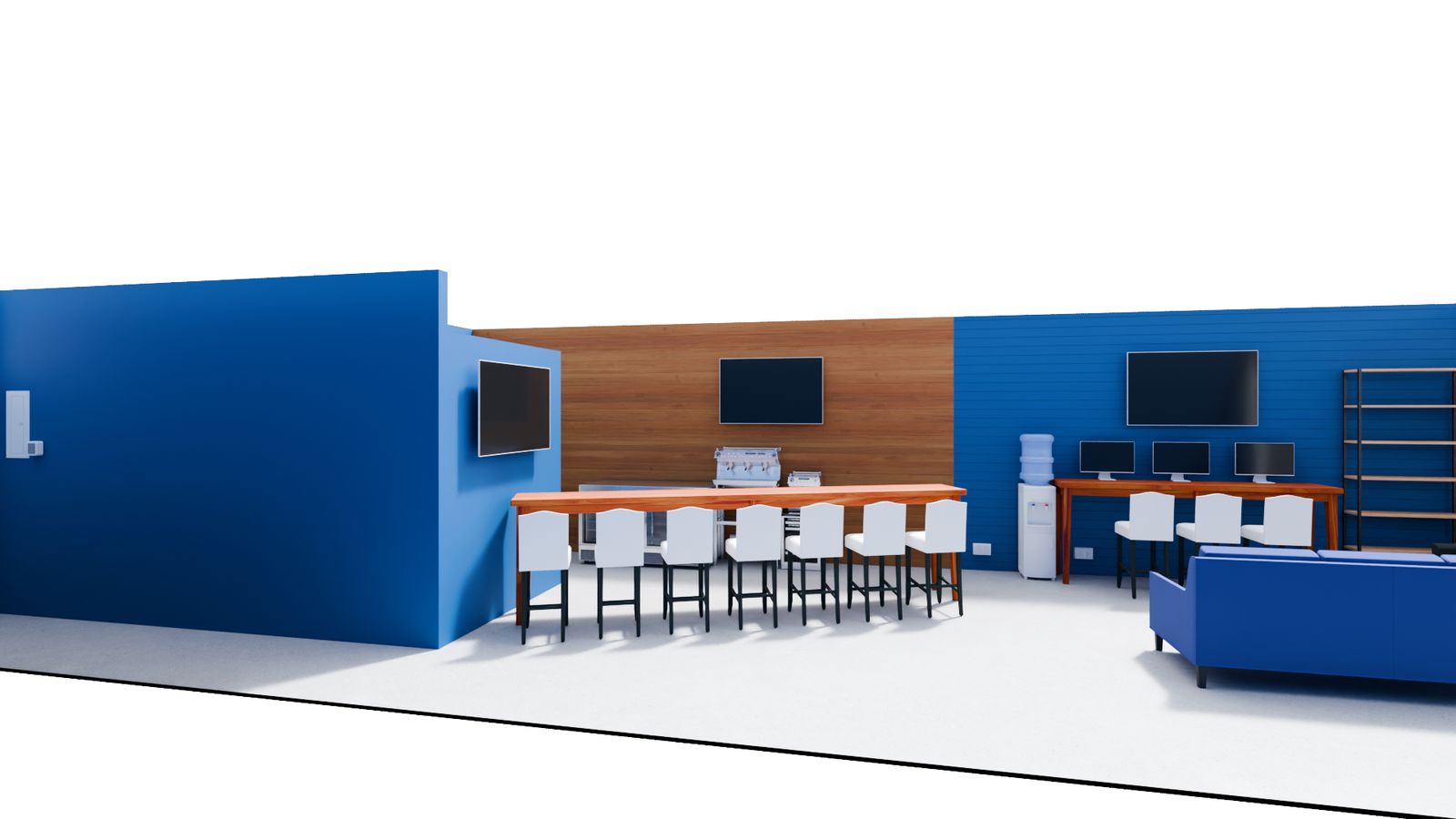
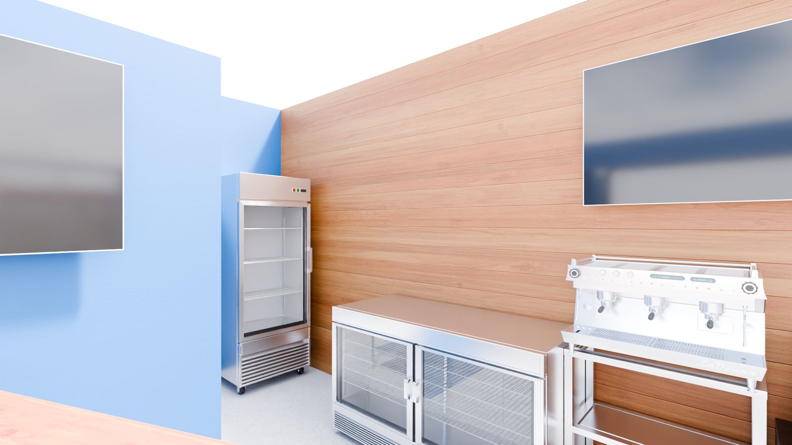
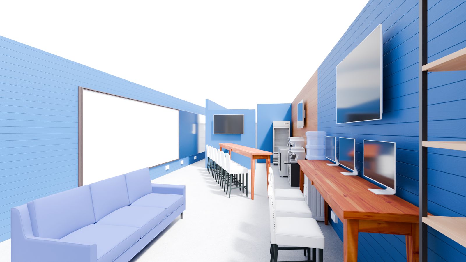
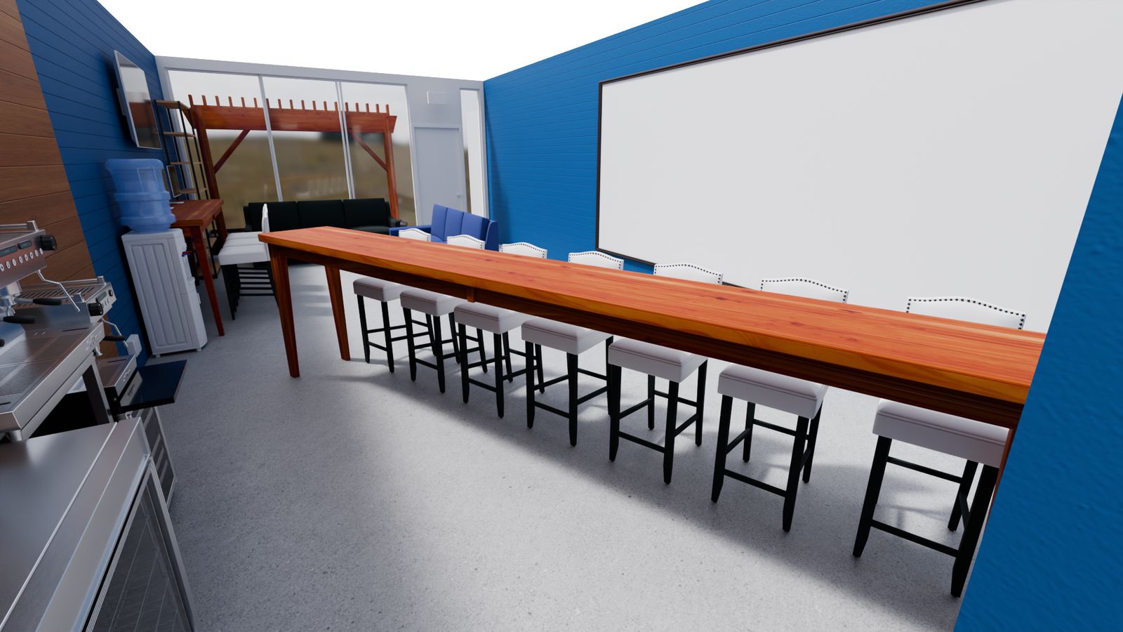
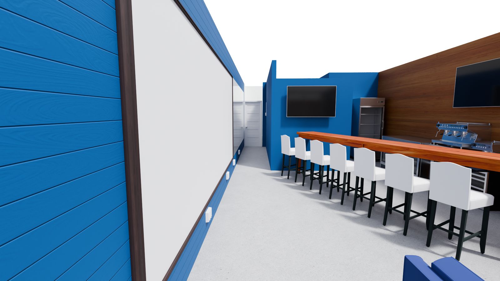
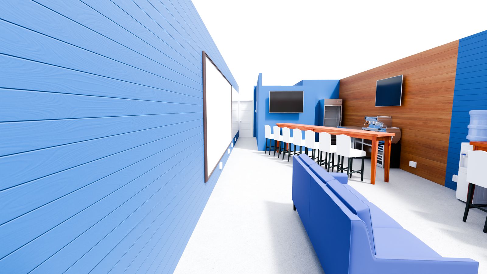
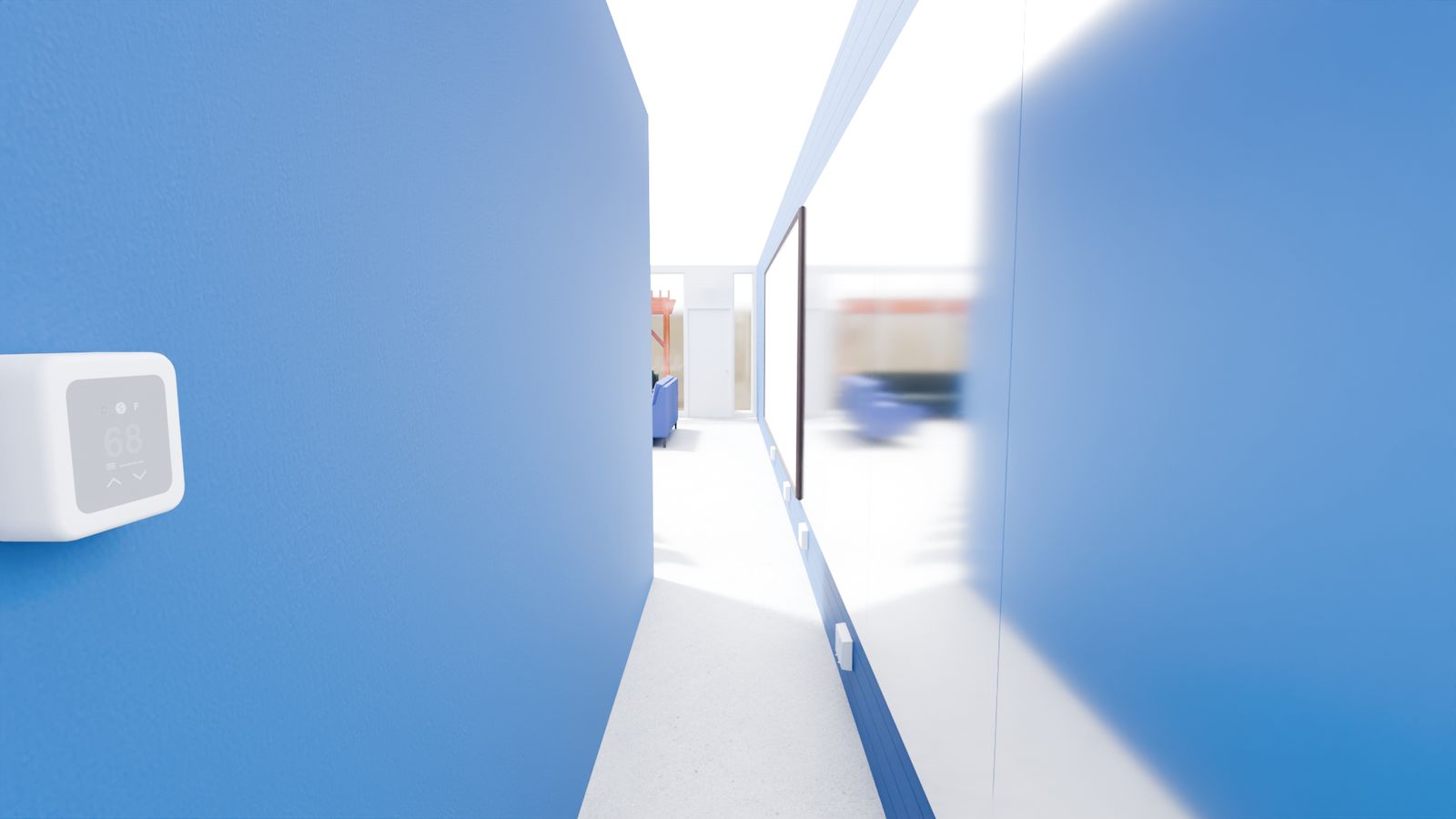
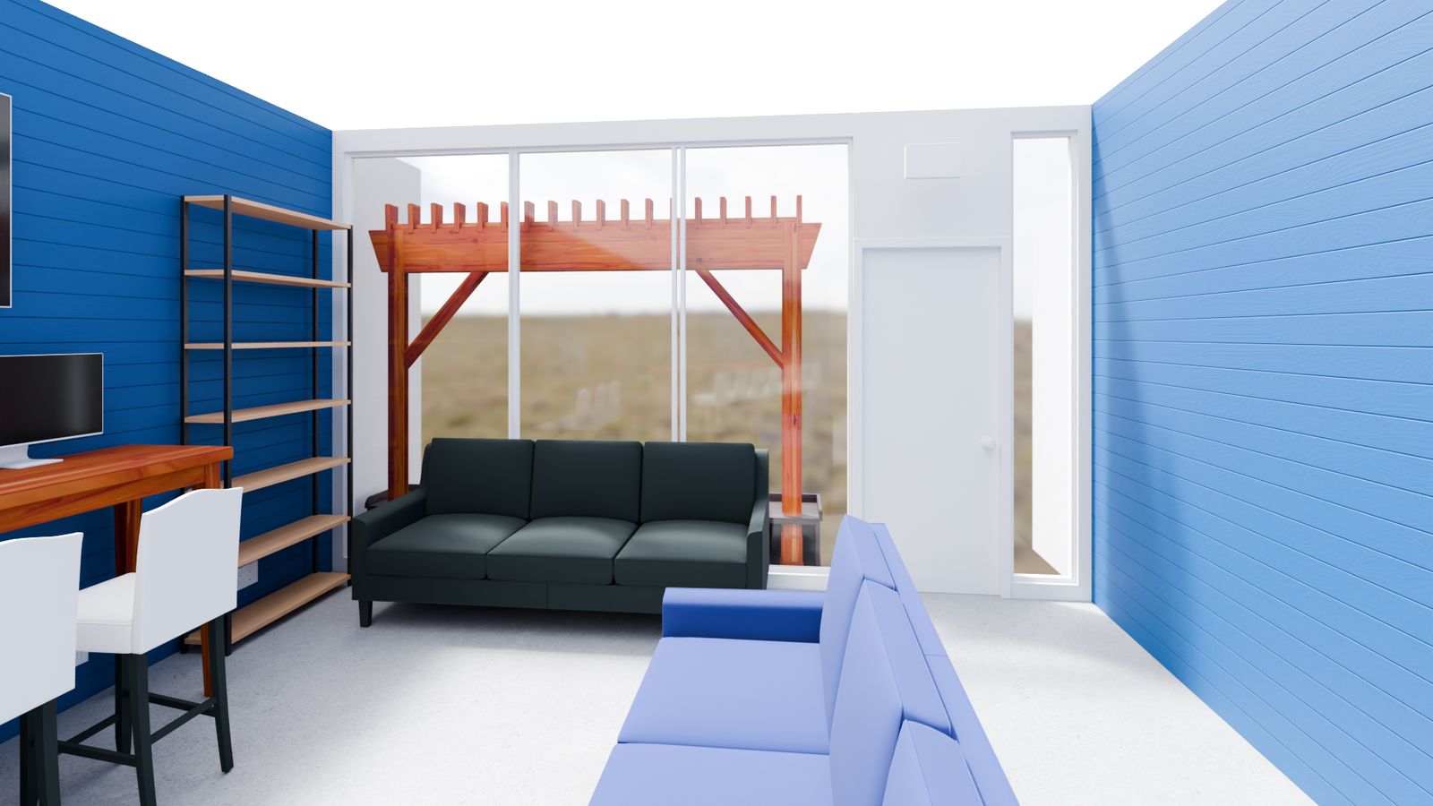
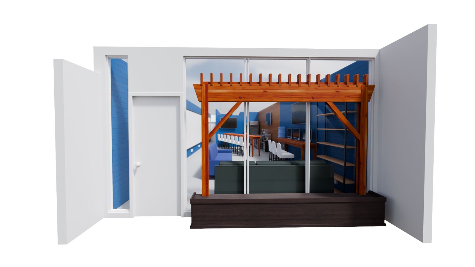
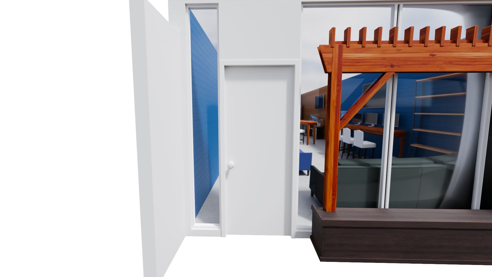
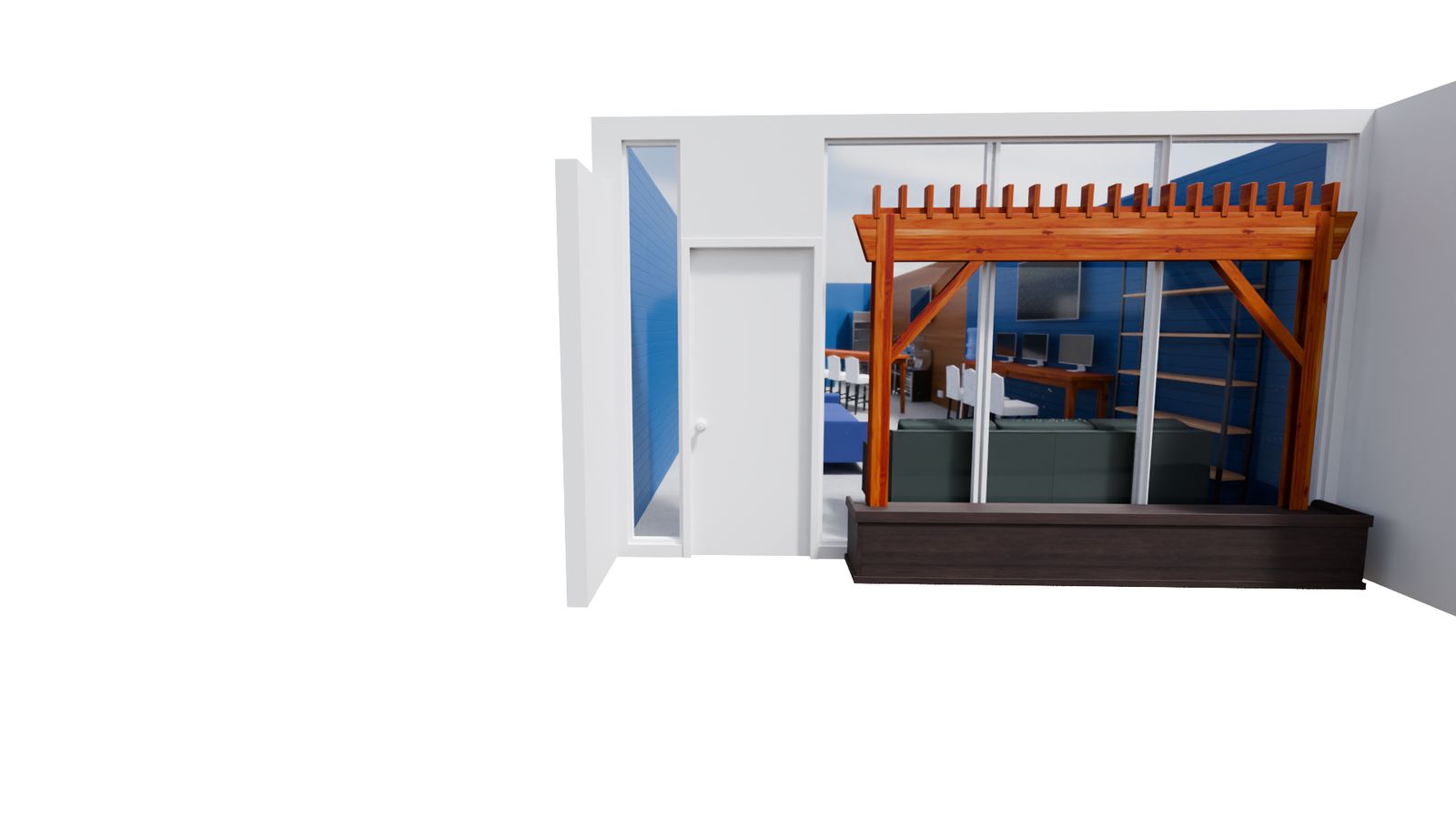
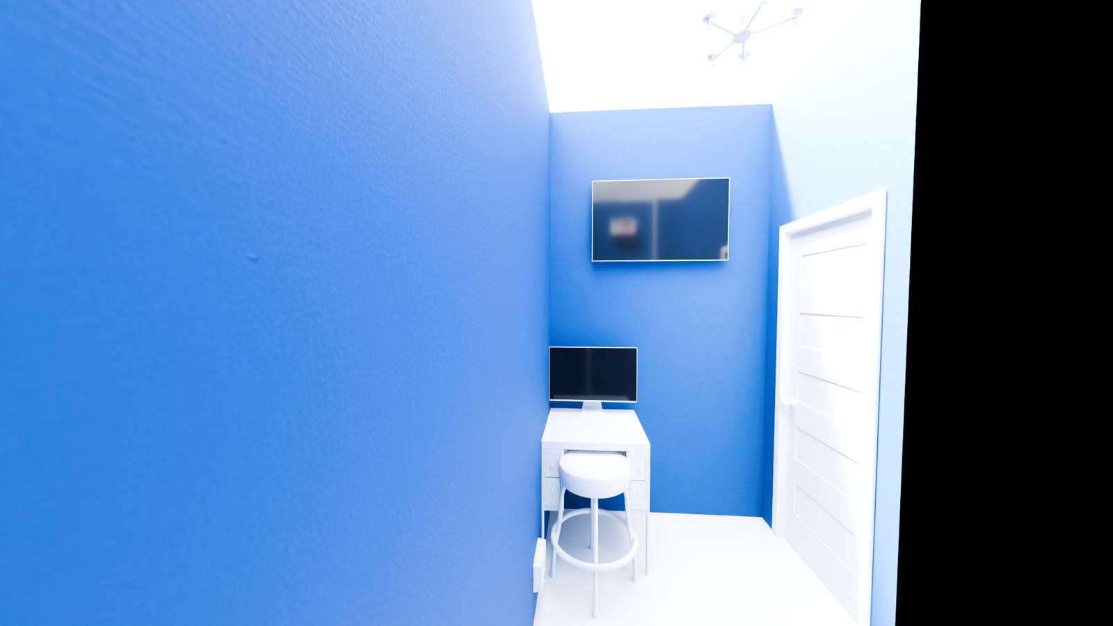
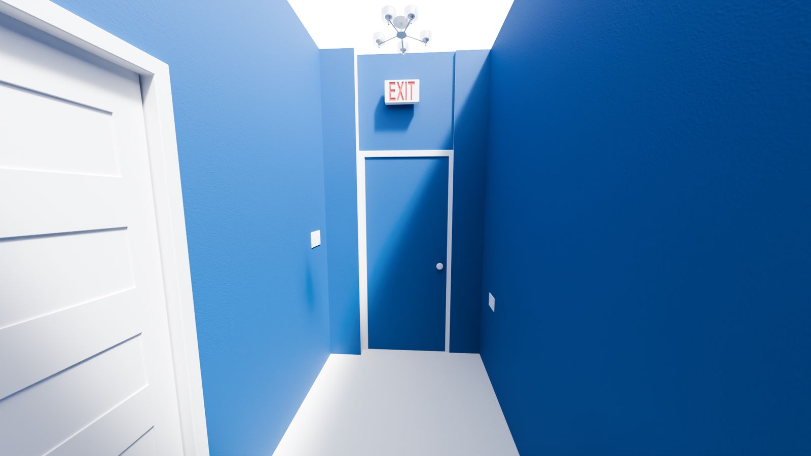
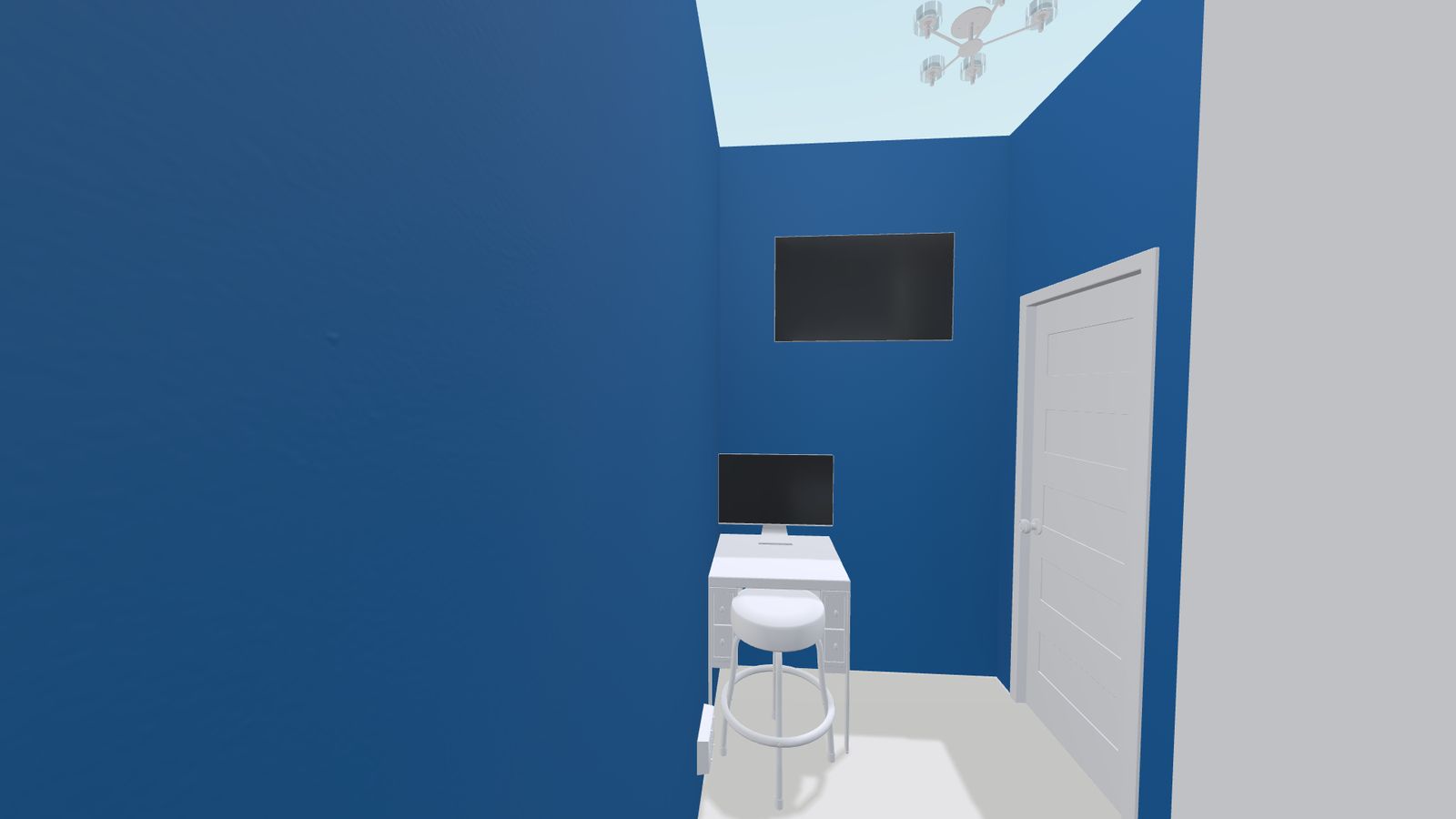
G. Proposed Design Renderings
Houzz/3D layout exports showing design intent for each area. Reference only; the as-stamped drawings govern. Click any image for full resolution.
Kitchen — Shows the new L-shaped kitchen wall (the headline new construction) and equipment layout.
Customer Restroom — Proposed max-extent-feasible layout: wall-mount corner sink, two ADA grab bars, FRP wall/ceiling lining. Existing toilet retained.
Employee Restroom — Second fixture set; same ADA framework.
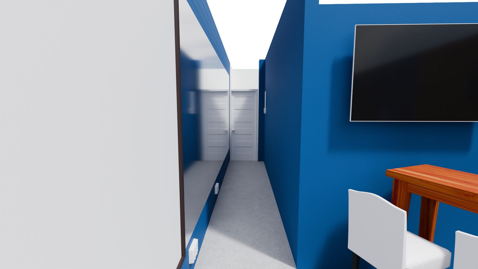
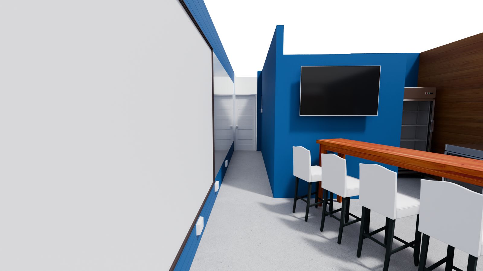
Bar Lounge — Main service area. 14-ft caster bar shown as movable equipment (N.I.C.); seating layout tuned to keep occupant load <50 (Group B).

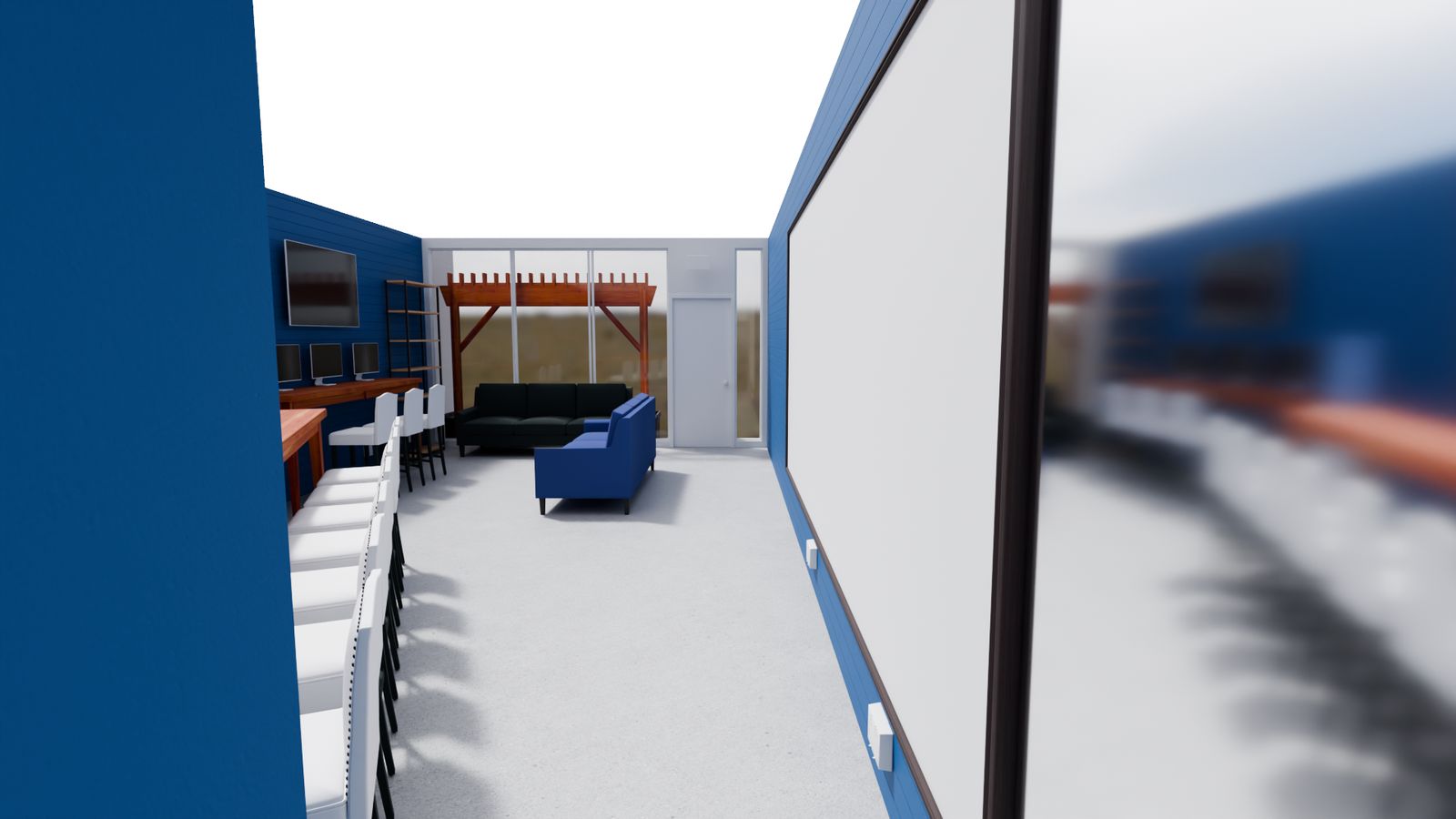
Pergola Lounge — Outdoor/pergola seating area.
Nick’s Office — Back-of-house office.
Source note: Building identity, vintage, permit, and structural facts are from the recorded 1965 City of Fort Lauderdale microfilm (Section F). Existing-condition facts are from direct site observation. Restroom configuration is documented as maximum extent feasible per ADA §202.3 / FBC-EB §306.6; a sealed technical-infeasibility memo accompanies the permit set (cite Access Board Guide to ADA Standards Ch. 2 (Feb. 2014) + DOJ Title II preamble on plumbing-wall infeasibility). Calculated items (occupant load, life-safety thresholds) are engineering estimates for your confirmation, not authority determinations.